Phasor
a phasor is a complex
number that represents the magnitude and phase of a
sinusoidal voltage or current
Phasors allow us to express
current-voltage relationships for inductors and capacitors much like we express
the current-voltage relationship for a resistor.
AC steady-state analysis using phasors allows us to express the relationship between current and voltage using a formula that looks like Ohm’s law:
V = I Z
Z is called impedance (units of ohms, W)
Impedance is (often) a complex number, but is not technically a phasor
Impedance depends on frequency, ω
I-V Relationship for a Resistor
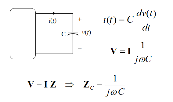
I-V Relationship for a Capacitor
I-V Relationship for an Inductor
Circuit
Element Phasor Relations
(ELI and ICE man)
(ELI and ICE man)
Phasor Diagrams
•A phasor diagram is just a graph of
several phasors on the complex plane (using real
and imaginary axes).
•A phasor diagram helps to visualize the
relationships between currents and voltages.
When two sine waves are produced on the same display, one wave is often said to be leading or lagging the other. This terminology makes sense in the revolving vector picture as shown in Figure 3. The blue vector is said to be leading the red vector or conversely the red vector is lagging the blue vector.
refer to this link for further information:


Now there is online tool for complex phasors of AC signals adding and drawing in both complex and time domain fashion. Please visit:
ReplyDeletehttp://www.cirvirlab.com/simulation/complex_number_phasor_addition_online.php#.UW-NycqzmhE