Saturday, March 17, 2012

The War of Currents


In November and December of 1887, Tesla filed for seven U.S. patents in the field of polyphase AC motors and power transmission. These comprised a complete system of generators, transformers, transmission lines, motors and lighting. So original were the ideas that they were issued without a successful challenge, and would turn out to be the most valuable patents since the telephone.


An adventurous Pittsburgh industrialist named George Westinghouse, inventor of railroad air brakes, heard about Tesla's invention and thought it could be the missing link in long-distance power transmission. He came to Tesla's lab and made an offer, purchasing the patents for $60,000, which included $5,000 in cash and 150 shares of stock in the Westinghouse Corporation. He also agreed to pay royalties of $2.50 per horsepower of electrical capacity sold. With more inventions in mind, Tesla quickly spent half of his newfound wealth on a new laboratory.


With the breakthrough provided by Tesla's patents, a full-scale industrial war erupted. At stake, in effect, was the future of industrial development in the United States, and whether Westinghouse's alternating current or Edison's direct current would be the chosen technology.


It was at this time that Edison launched a propaganda war against alternating current. Westinghouse recalled:


I remember Tom [Edison] telling them that direct current was like a river flowing peacefully to the sea, while alternating current was like a torrent rushing violently over a precipice. Imagine that! Why they even had a professor named Harold Brown who went around talking to audiences... and electrocuting dogs and old horses right on stage, to show how dangerous alternating current was.
Meanwhile, a murderer was about to be executed in the first electric chair at New York's Auburn State Prison. Professor Brown had succeeded in illegally purchasing a used Westinghouse generator in order to demonstrate once and for all the extreme danger of alternating current. The guinea pig was William Kemmler, a convicted ax-murderer, who died horribly on August 6, 1890, in "an awful spectacle, far worse than hanging." The technique was later dubbed "Westinghousing."


In spite of the bad press, good things were happening for Westinghouse and Tesla. The Westinghouse Corporation won the bid for illuminating The Chicago World's Fair, the first all-electric fair in history. The fair was also called the Columbian Exposition — in celebration of the 400th Anniversary of Columbus discovering America. Up against the newly formed General Electric Company (the company that had taken over the Edison Company), Westinghouse undercut GE's million-dollar bid by half. Much of GE's proposed expenses were tied to the amount copper wire necessary to utilize DC power. Westinghouse's winning bid proposed a more efficient, cost-effective AC system.


The Columbian Exposition opened on May 1, 1893. That evening, President Grover Cleveland pushed a button and a hundred thousand incandescent lamps illuminated the fairground's neoclassical buildings. This "City of Light" was the work of Tesla, Westinghouse and twelve new thousand-horsepower AC generation units located in the Hall of Machinery. In the Great Hall of Electricity, the Tesla polyphase system of alternating current power generation and transmission was proudly displayed. For the twenty-seven million people who attended the fair, it was dramatically clear that the power of the future was AC. From that point forward more than 80 percent of all the electrical devices ordered in the United States were for alternating current.

Wednesday, March 14, 2012

Phase Difference


   The phase difference or phase shift as it is also called of a sinusoidal waveform is the angle Φ (Greek letter Phi), in degrees or radians that the waveform has shifted from a certain reference point along the horizontal zero axis. In other words phase shift is the lateral difference between two or more waveforms along a common axis and sinusoidal waveforms of the same frequency can have a phase difference.
   The phase difference, Φ of an alternating waveform can vary from between 0 to its maximum time period, T of the waveform during one complete cycle and this can be anywhere along the horizontal axis between, Φ = 0 to 2π (radians) or Φ  = 0 to 360o depending upon the angular units used. Phase difference can also be expressed as a time shift of τ in seconds representing a fraction of the time period, T for example, +10mS or - 50uS but generally it is more common to express phase difference as an angular measurement.
    Then the equation for the instantaneous value of a sinusoidal voltage or current waveform we developed in the previousSinusoidal Waveform  will need to be modified to take account of the phase angle of the waveform and this new general expression becomes. 

Phase Difference Equation 


Phase Angle

  • Where:
  •   Am  -  is the amplitude of the waveform.
  •   ωt  -  is the angular frequency of the waveform in radian/sec.
  •   Φ (phi)  -  is the phase angle in degrees or radians that the waveform has shifted either left or right from the
  •                     reference point.
If the positive slope of the sinusoidal waveform passes through the horizontal axis "before" t = 0 then the waveform has shifted to the left so Φ >0, and the phase angle will be positive in nature. Likewise, if the positive slope of the sinusoidal waveform passes through the horizontal axis "after" t = 0 then the waveform has shifted to the right so Φ <0, and the phase angle will be negative in nature and this is shown below.

Phase Relationship of a Sinusoidal Waveform


Phase Relationship of a Sine Wave


Firstly, lets consider that two alternating quantities such as a voltage, v and a current, i have the same frequency ƒ in Hertz. As the frequency of the two quantities is the same the angular velocity, ω must also be the same. So at any instant in time we can say that the phase of voltage, v will be the same as the phase of the current, i. Then the angle of rotation within a particular time period will always be the same and the phase difference between the two quantities of v and i will therefore be zero and Φ = 0. As the frequency of the voltage, v and the current, i are the same they must both reach their maximum positive, negative and zero values during one complete cycle at the same time (although their amplitudes may be different). Then the two alternating quantities, v and i are said to be "in-phase".

Two Sinusoidal Waveforms - "in-phase"


Two Sinusoidal Waveforms that are In-phase


Now lets consider that the voltage, v and the current, i have a phase difference between themselves of  30o, so (Φ  = 30o orπ/6 radians). As both alternating quantities rotate at the same speed, i.e. they have the same frequency, this phase difference will remain constant for all instants in time, then the phase difference of  30o between the two quantities is represented by phi, Φ as shown below.

Phase Difference of a Sinusoidal Waveform


Phase Difference of two Sine Waves


The voltage waveform above starts at zero along the horizontal reference axis, but at that same instant of time the current waveform is still negative in value and does not cross this reference axis until 30o later. Then there exists a Phase difference between the two waveforms as the current cross the horizontal reference axis reaching its maximum peak and zero values after the voltage waveform. As the two waveforms are no longer "in-phase", they must therefore be "out-of-phase" by an amount determined by phi, Φ and in our example this is 30o. So we can say that the two waveforms are now30o out-of phase. The current waveform can also be said to be "lagging" behind the voltage waveform by the phase angle,Φ. Then in our example above the two waveforms have a Lagging Phase Difference so the expression for both the voltage and current above will be given as.


Lagging Phase Difference


  where, i lags v by angle Φ
Likewise, if the current, i has a positive value and crosses the reference axis reaching its maximum peak and zero values at some time before the voltage, v then the current waveform will be "leading" the voltage by some phase angle. Then the two waveforms are said to have a Leading Phase Difference and the expression for both the voltage and the current will be.


Leading Phase Difference


  where, i leads v by angle Φ
The phase angle of a sine wave can be used to describe the relationship of one sine wave to another by using the terms "Leading" and "Lagging" to indicate the relationship between two sinusoidal waveforms of the same frequency, plotted onto the same reference axis. In our example above the two waveforms are out-of-phase by 30o so we can say that i lags v or vleads i by 30o. The relationship between the two waveforms and the resulting phase angle can be measured anywhere along the horizontal zero axis through which each waveform passes with the "same slope" direction either positive or negative. In AC power circuits this ability to describe the relationship between a voltage and a current sine wave within the same circuit is very important and forms the bases of AC circuit analysis.


The Cosine Waveform

So we now know that if a waveform is "shifted" to the right or left of 0o when compared to another sine wave the expression for this waveform becomes Am sin(ωt ± Φ). But if the waveform crosses the horizontal zero axis with a positive going slope90o or π/2 radians before the reference waveform, the waveform is called a Cosine Waveform and the expression becomes.

Cosine Expression


Cosine Wave


The Cosine Wave, simply called "cos", is as important as the sine wave in electrical engineering. The cosine wave has the same shape as its sine wave counterpart that is it is a sinusoidal function, but is shifted by +90o or one full quarter of a period ahead of it.

Phase Difference between a Sine wave and a Cosine wave


Phase Difference between a sine and a cosine wave


Alternatively, we can also say that a sine wave is a cosine wave that has been shifted in the other direction by -90o. Either way when dealing with sine waves or cosine waves with an angle the following rules will always apply.

Sine and Cosine Wave Relationships


Sine Wave and Cosine Wave Relationships


When comparing two sinusoidal waveforms it more common to express their relationship as either a sine or cosine with positive going amplitudes and this is achieved using the following mathematical identities.


Sine and Cosine Identities


AC Resistance with a Sinusoidal Supply


AC Resistance in an AC Circuit


When the switch is closed, an AC voltage, V will be applied to resistor, R. This voltage will cause a current to flow which in turn will rise and fall as the voltage rises and falls. The current and voltage will both reach their maximum or peak values and fall through zero at exactly the same time, i.e. they rise and fall simultaneously and are therefore said to be "in-phase ". Then the electrical current that flows through an AC resistance varies sinusoidally with time and is represented by the expression, I(t) = Im x cos(ωt + θ), where Im is the maximum amplitude of the current and θ is its phase angle. In addition we can also say that for any given current, i  flowing through the resistor the maximum or peak voltage across the terminals of R will be given by Ohm's Law as:


Voltage across the Resistance


and the instantaneous value of the current, i will be:


Current through the Resistance


So for a purely resistive circuit the AC current flowing through the resistor varies in proportion to the applied voltage across it following the same sinusoidal pattern. As the supply frequency is common to both the voltage and current, their phasors will also be common resulting in the current being "in-phase" with the voltage, ( θ = 0 ). In other words, there is no phase difference between the current and the voltage when using an AC resistance as the current will achieve its maximum, minimum and zero values whenever the voltage reaches its maximum, minimum and zero values as shown below.


Sinusoidal Waveforms for AC Resistance


Sinusoidal Waveforms for AC Resistance


This effect can also be represented by a phasor diagram. In the complex domain, resistance is a real number only meaning that there is no "j" or imaginary component. Therefore, as the voltage and current are both in-phase with each other, as there is no phase difference ( θ = 0 ), so the vectors of each quantity are drawn super-imposed upon one another along the same reference axis. The transformation from the sinusoidal time-domain into the phasor-domain is given as.


Phasor Diagram for AC Resistance


Phasor Diagram for AC Resistance


As a phasor represents the RMS values of the voltage and current quantities unlike a vector which represents the peak or maximum values, dividing the peak value of the time-domain expressions above by 2 the corresponding voltage-current phasor relationship is given as.


RMS Relationship


Magnitude Relationship between Voltage and Current


Phase Relationship


Phase Relationship between Voltage and Current\


This shows that a pure resistance within an AC circuit produces a relationship between its voltage and current phasors in exactly the same way as it would relate the same resistors voltage and current relationship within a DC circuit. However, in an sinusoidal AC circuit this voltage-current relationship is now called Impedance while it is commonly called Resistancein a DC circuit as defined by Ohm's Law. In both cases this voltage-current ( V-I ) relationship is always linear in a pure resistance. So when using resistors in AC circuits the term Impedance, symbol Z is the generally used and we can say that DC resistance = AC impedance, R = Z.
The impedance vector is represented by the letter, ( Z ) for an AC resistance value with the units of Ohm's (Ω) the same as for DC. Then Impedance (AC resistance) is defined as:


AC Impedance


Impedance Vector


Impedance can also be represented by a complex number as it depends upon the frequency of the circuit, ω when reactive components are present. But in the case of a purely resistive circuit this reactive component will always be zero and the general expression for impedance in a purely resistive circuit given as a complex number will be.


Z = R + j0 = R Ω's


Since the phase angle between the voltage and current in a purely resistive AC circuit is zero, the power factor must also be zero and is given as: cos 0o = 1.0. Then the instantaneous power consumed in the resistor is given by


Power in a Purely Resistive Circuit


However, as the average power in a resistive or reactive circuit depends upon the phase angle and in a purely resistive circuit this is equal to θ = 0, the power factor is equal to one so the average power consumed by an AC resistance can be defined simply by using Ohm's Law as:


Ohms Law for Power


which are the same Ohm's Law  equations as for DC circuits. Then the effective power consumed by an AC resistance is equal to the power consumed by the same resistor in a DC circuit.
Many AC circuits such as heating elements and lamps consist of a pure ohmic resistance only and have negligible values of inductance or capacitance containing on impedance. In such circuits we can use both Ohm's Law , Kirchoff's Law  as well as simple circuit rules for calculating the voltage, current, impedance and power as in DC circuit analysis. When working with such rules it is usual to use RMS values only.

Monday, March 12, 2012

Phasor Relationships

Phasor
a phasor is a complex number that represents the magnitude and phase of a sinusoidal voltage or current
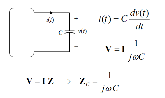
Phasors allow us to express current-voltage relationships for inductors and capacitors much like we express the current-voltage relationship for a resistor.

AC steady-state analysis using phasors allows us to express the relationship between current and voltage using a formula that looks like Ohm’s law:

V = I Z

Z is called impedance (units of ohms, W)

Impedance is (often) a complex number, but is not technically a phasor

Impedance depends on frequency, ω


I-V Relationship for a Resistor


  I-V Relationship for a Capacitor


  I-V Relationship for an Inductor


Circuit Element Phasor Relations
(ELI and ICE man)


Phasor Diagrams
A phasor diagram is just a graph of several phasors on the complex plane (using real and imaginary axes).
•A phasor diagram helps to visualize the relationships between currents and voltages.


          When two sine waves are produced on the same display, one wave is often said to be leading or lagging the other. This terminology makes sense in the revolving vector picture as shown in Figure 3. The blue vector is said to be leading the red vector or conversely the red vector is lagging the blue vector. 


refer to this link for further information:


Alternating Current


Alternating Current            

         AC is short for alternating current. This means that the direction of current flowing in a circuit is constantly being reversed back and forth. This is done with any type of AC current/voltage source.

        The electrical current in your house is alternating current. This comes from power plants that are operated by the electric company. Those big wires you see stretching across the countryside are carrying AC current from the power plants to the loads, which are in our homes and businesses. The direction of current is switching back and forth 60 times each second.


  Electrons alternate directions in AC electricity


With an AC generator, a slightly different configuration alternates the push and pull of each generator terminal. Thus the electricity in the wire moves in one direction for a short while and then reverses its direction when the generator armature is in a different position.


This illustration gives an idea of how the electrons move through a wire in AC electricity. Of course, both ends of the wire extend to the AC generator or source of power.


AC movement of electrons in wire


       The charge at the ends of the wire alternates between negative (−) and positive (+). If the charge is negative (−), that pushes the negatively charged electrons away from that terminal. If the charge is positive (+), the electrons are attracted in that direction.


Advantages of AC electricity

      There are distinct advantages of AC over DC electricity. The ability to readily transform voltages is the main reason we use AC instead of DC in our homes.


Transforming voltages

     The major advantage that AC electricity has over DC electricity is that AC voltages can be readily transformed to higher or lower voltage levels, while it is difficult to do that with DC voltages.
     Since high voltages are more effecient for sending electricity great distances, AC electricity has an advantage over DC. This is because the high voltages from the power station can be easily reduced to a safer voltage for use in the house.
     Changing voltages is done by the use of a transformer. This device uses properties of AC electromagnets to change the voltages.
(See AC Transformers for more information.)


Tuning circuits

     AC electricity also allows for the use of a capacitor and inductor within an electrical or electronic circuit. These devices can affect the way the alternating current passes through a circuit. They are only effective with AC electricity.
     A combination of a capacitor, inductor and resistor is used as a tuner in radios and televisions. Without those devices, tuning to different stations would be very difficult.


Add caption